Sunday, 29 April 2012

Assessment 1 Progression - Pump Action Bottle

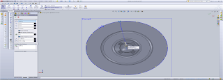
I have made a slow but steady approach towards the pump action bottle. In the screenshot below I'm currently using the circular sketch pattern I created five lines which intersected both parts of the tube piece. From there I used the rib feature which created the five boulder parts of the tube piece.


The piece below is the passage where the soap passes through as the pump is maneuvered. The passages are where the cuts on the piece are shown, as well as the highlighted area, which is just about to be cut through. I hid the surrounding tube piece so that this process of making this part was easier to see and simpler to build.


Below is the section view through the tube piece. If you look closely you can see that the part I had just been creating in the previous image is in its correct position. I find the section view to be very helpful in understanding the full dimensioning of the part your creating.


Now that the basic structure of the pump tube has been completed I then finished off the very top of the tube with a few extruded cuts to represent the soap bottle I was modelling. In the image below, you can see through the centre of the tube representing the piece I was modelling two images above.


Now that the first part of the pump action bottle was complete (The tube piece), it was time to progress through and complete the other required parts of the bottle. In the image below I created three quarters of a circle, used the swept/boss base feature to create the bottom of the spring. Going through the lecture which showed the process of creating the spring was very helpful in this section of the bottle.


I managed to create a plane at one end of the three quarter circle part and then draw a helix with the desired amount of revolutions and height of the pitch. Once I had created it, I then created a plane at one end point of spiral and used the swept/boss base feature to model the spring. The image below is the final representation of the spring.


I'm now at the stage of creating the top piece of the bottle. In the image below you can see underneath the top piece. Firstly to create the main top piece structure I used a series of lofts and guide curves to create the desired shape. From there I extruded a cylinderical pipe which will lead to the main tube piece of the bottle.


Progressing through the top piece of the bottle still I have detailed the cylinderical part with a series of cuts and fillets to match the bottle. The tools which I used throughout this section of modelling was the convert entities and offset entities. These tools made the progress of this bottle a lot more accurate and precise.


Finally completely each of the four parts which make up the the pump action bottle I'm now at the stage of creating an accurate assembly of the parts. In the image below, I have been able to carefully mate each piece together successfully.


Sunday, 22 April 2012

Second Progress Post


Throughout the progress of the shampoo bottle that I was doing I had a bit of trouble with the top cap and the main head of the bottle. Configuring how to create the top cap separate from the main head piece was one of the problems I had. Finally after a bit of research and a bit of help I created a new plane, used the convert entities tool and created the part above the main head piece. From there I used the split tool and split and saved each piece separately.


Finally managing to complete each of the three pieces of the shampoo bottle successfully; the body, head and top cap, I have now completed the assembly of the three parts and have completed the first stage of the shampoo bottle as you can see from the picture above. With the problems and challenges that I came across in this task of the assessment I have learnt quite a lot in terms of over coming problems myself and finding different ways around things.


When it came to designing the customized piece of the bottle I simply used the same head and top cap but then created a complete new body. I took into considering how slim the actual shampoo bottle looked and decided to customize my own to look a lot more thick and solid, as you can see above. The process of constructing this body of the bottle was a lot easier due to firstly creating the main shampoo bottle. Using the same techniques and tools everything was a lot more straight forward.


Tuesday, 17 April 2012

SolidWorks Progress for Assessment 1


Due to surgical extractions in weeks 2 and 3 I was unable to come to a successful start. However in following weeks I began to make some progress. In the image above, you can see I have begun development on the non-cylinderical shampoo bottle for assessment 1. I applied 4 images, front, side, top and bottom and used them as guides to loft together the shampoo bottle. Using these lines as guide curves I was able to loft the shampoo bottle together giving it a 3D structure.


The image above is the outcome of successfully lofting together the shampoo bottle.


The next step was to split the top of the bottle from the body of the bottle and to begin development on the lid of the bottle.


In the image above I have successfully past the point of splitting the lid from the body and have begun development of the lid underneath.


In this image I have constructed the main structure inside the lid as you can see and am now finishing it off by placing the two ribs either side to give the lid its structural integrity.


The above image is the real cap.

More progress to come.

Thanks, Kieren.